This post was written for
studying. There maybe a lot wrong going on.
목차
- OSI layer in Datacenter
- Flow Control
- Types of Networks
- Network Topology Overview
- Top-of-Rack (ToR) Switch with Out-of-Band (OOB) Management
- Fiber Connectors and Transceivers in Datacenters
- Single-Mode (SM) vs Multi-Mode (MM)
OSI layer in Datacenter
The Physical layer (Layer 1) encompasses the actual hardware, including cables (like Ethernet and fiber optics) and other devices that facilitate the physical transfer of electrical or optical signals. This layer is crucial for ensuring high bandwidth and low latency connections between servers and network equipment.
Aside from the physical cable, Repeaters and Hubs also operate at this layer. A Repeater simply repeats a signal from one medium to the other, allowing a sereis of cables to be dasiy chained together and increase the range a signal can travel beyond the single cable limit. A Hub is simply a multi-port Repeater. If four devices are connected to a single Hub, anythins sent by one device gets repeated to the other three.
The Data Link layer (Layer 2) is responsible for node-to-node communication and error detection/correction. In data centers, Top-of-Rack (ToR) switches operate at this layer, managing data frames between servers and handling tasks like VLAN tagging and MAC address filtering to create logical network segments. This layer helps to optimize bandwidth utilization and improve security by isolating traffic between different virtual networks.
Moving to the Network layer (Layer 3), this layer manages logical addressing and routing of data packets. Routers and Layer 3 switches in a data center ensure that data is directed correctly between different subnets and external networks. They utilize IP addressing and routing protocols to facilitate communication across the data center and between other locations, playing a critical role in the overall network topology, including Clos architectures
At the Transport layer (Layer 4), protocols such as TCP and UDP ensure reliable end-to-end communication. This layer handles flow control, error correction, and data segmentation, which are essential for applications that require dependable data transmission, such as file transfers, streaming, and database communications.
The Session layer (Layer 5) is responsible for managing sessions between applications, ensuring that connections remain stable and synchronized.
The Presentation layer (Layer 6) transforms data into a format that applications can understand, including tasks such as data encryption and compression. This layer is particularly important for security in data centers, as it handles encryption protocols like SSL/TLS to protect sensitive information during transmission and ensures efficient data transfer by compressing large data sets.
Finally, the Application layer (Layer 7) interfaces directly with user applications and services, managing protocols such as HTTP, FTP, and DNS. In a data center, this layer is crucial for delivering applications to end-users and for the operation of services such as load balancers and application firewalls that optimize traffic flow and enhance security. The Application layer ensures that user requests are routed to the appropriate servers and services, enabling seamless interaction and high availability.
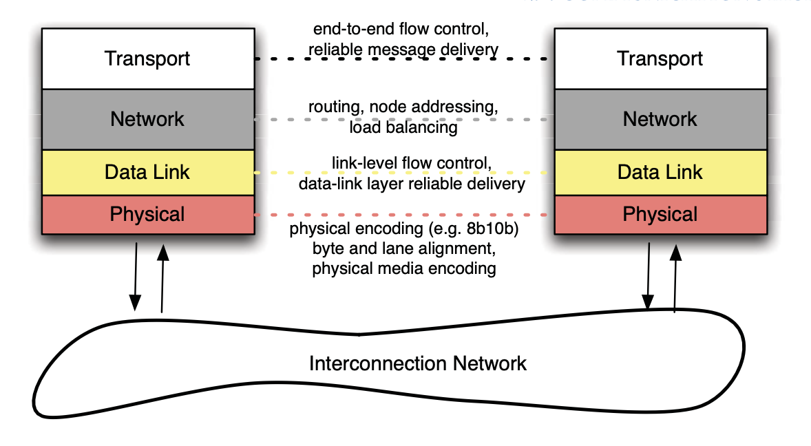
Flow Control
The basic mechanism by which resources in the network are managed is flow control. Flow control provides a simple accounting method for managing resources that are in demand by multiple uncoodrdinated sources. When a resource is requested but not currently available for use, we can drop the request and all subsequent requests until the resource is freed, or block and wait for the request to free
Types of Networks
Topologies can be broken down into two different genres: direct and indirect. A direct network has processing nodes attached directly to the switching fabric; that is, the switching fabric is dis- tributed among the processing nodes. An indirect network has the endpoint network independent of the endpoints themselves – i.e., dedicated switch nodes exist and packets are forwarded indirectly through these switch nodes. The type of network determines some of the packaging and cabling requirements as well as fault resilience. It also impacts cost, for example, since a direct network can combine the switching fabric and the network interface controller (NIC) functionality in the same silicon package. An indirect network typically has two separate chips, with one for the NIC and another for the switching fabric of the network.
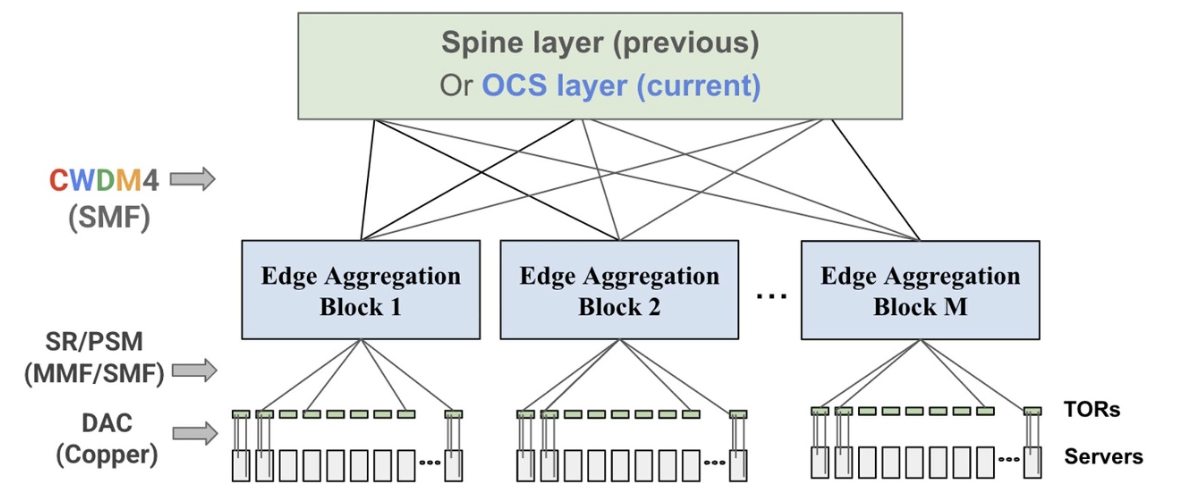
Network Topology Overview
- Leaf Layer (ToR Switches)
This is the first layer of switches, ToR switches. Each ToR switch connects directly to a rack of servers. This forms the leaf layer, where each rack is its own independent unit
- Spine Layer
The Spine layer consists of high-capacity switches that connect multiple leaf switches. These are the central “hubs” that allow leaf switches to communicate with one another. Every ToR switch connects to multiple spine switches, creating multiple redundant paths for traffic. This ensures that even if one spine switch fails, traffic can still be routed through another.
- Core layer
The core layer connects multiple spine switches together, providing even more redundancy and scalability. This layer is primarily responsible for connecting differnet clusters or zones within the datacenter. The core layer ensures that traffic between different paths of the datacenter can still flow efficiently, even as the network scales to include more devices.
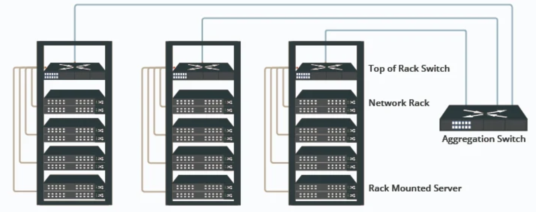
Top-of-Rack (ToR) Switch with Out-of-Band (OOB) Management
ToR Swtich Overview
A ToR switch sits at the top of each server rack in a datacenter and is responsible for connecting all the servers in the rack to the broader network, typically through high-speed connections (10G, 40G, 100G, or even 400G ports).
How OOB Management Works with ToR Switches
Physical Separation
-
Data Plane: Handles production traffic for the servers in the rack, connecting them to the core or spine switches. The data plane is responsible for the actual transmission of packets between servers, clients, and external network
-
Management Plane(OOB): Operates on a seperate physical interface from the data plane, ensuring that management traffic does not interface with or depend on the production network. The OOB management network can be accessed through dedicated Ethernet ports on the ToR switches that connect directly to an OOB network.
Centeralized Management
-
ToR switches with OOB management are connected to a centralized management console. This console allows network administrators to access the management interfaces of all ToR swithces via the OOB network.
-
This centralized system typically includes access to SSH for configuration and monitoring of the switches.
Configuration & Updates
-
Firmware upgrades, configuration changes, and patching of ToR switches can all be carried out via OOB management, ensuring that these tasks can be performed even during peak load time without affecting the data plane.
-
Because the management network is isolated, these activities won’t interface with normal data operations, reducing the risk of disruptions.
Connectivity
Patch panels are often between the servers and the ToR switch to improve cable management and organization. They allow for easy patching and cable changes without directly interfering with the switch or servers.
Server-to-Tor Connectivity
Servers connect to the ToR switch using Copper Ethernet cables (Cat6/Cat6a) for distance within the rack or fiber optic cables for high-speed connections. The most common server interface are 10GBASE-T Etherent, 25G, or 40G depending on the performacne requirements of the datacenter.
-
Copper Cables (Cat6/Cat6a) external link: These are often used to connect servers to the ToR switch within the same rack.
-
Twinax (DAC): A cost-effective and low-power option for short range connections between servers and ToR switch, often used for 10G, 25G, or 40G connections.
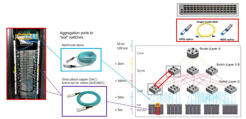
ToR-to-Spine Connectivity
The uplinks from the ToR switch to the spine switches are usually fiber optic cables (SMF). These uplink are typically 40G, 100G, or even 400G
-
Fiber Optic Cables: Used for connecting ToR switches to spine siwtches in a leaf-spine architecture. The fiber optic uplinks ensure high-speed, long-distance transmission across the datacenter.
-
SMF: It is commonly used for distacnes exceeding 100 meters, especially for 100G and 400G connections.
-
MMF: It can be used for shorter distances (up to around 100 meters), but it’s less common in newer datacenters that require high bandwidth and scalability
Fiber Connectors and Transceivers in Datacenters
Fiber Connector
Connectors are used to join fiber optic cables to devices like transceivers, patch panels, and switches. The connectors need to precisely align the fiber cores to ensure efficient data transmission.
- LC (Lucent Connector)
LC connectors are widely used in datacenters due to thier small form factor and high density. Commonly found in SFP transceivers for both SM and MM fiber. LC connectors are popular for high-density patch panels and connections between switches, servers, and storage devices.
Common with SFP and QSFP transceivers, used for both SM and MM fiber
- MTP/MPO (Multi-Fiber Push On)
MTP is multi-fiber connector, designed to connect multiple fibers (typically 12 or 24 fibers) within a single connector. It is often used for high-speed parallel optical transmissions like 40GBASE-SR4 and 100GBASE-SR10, as well as for structured cabling in datacenters. It is ideal for environments requiring a lot of fiber connections in a small space, such as between aggregation switches or between the core and spine layers in large datacenters.
Used with QSFP+, QSFP28, or QSFP-DD transceivers for parallel optics in high speed connections
Fiber Transceiver
Transceivers convert electrical signals into optical signals for transmission over fiber optics and then convert optical signals back into electrical signals at the receiving end.
- SFP
SFP transeivers are widely used in 1G and 10G Ethernet switches, routers, and NICs within datacenters. They’re modular, allowing for easy upgrades and replacements.
- QSFP
These are commonly used in core, spine, and leaf switches where higher bandwidth is required. The QSFP+ transceivers often use MTP/MPO connectors for parellel transmission of data.
- CWDM/DWDM Transceivers
CWDM and DWDM transceivers support various data rate from 1G to 100G. They use different wavelengths of light to transmit multiple singals over a single SM fiber, greatly increasing the fiber’s capacity. It is used in long-distance connections between datacenters or for high-bandwidth backbone links, as they allow many channels to be carried over a single fiber pair.
DWDMs are primarily used as encryptors and decryptor, but they are also used to aggregate multiple network connections into a single fiber pair. These devices are generally used to connect AZs to each other.
Single-Mode (SM) vs Multi-Mode (MM)
Increasing Bandwidth Demands
Datacenters are handling larger volumes of data with increasing speeds (e.g, 100G, 200G, 400G, and higher). Single-Mode (SM) fiber is better suited for these higher data rates over longer distances, offering better performance at higher speeds. MM fiber has limitations in terms of bandwidth and distance due to modal dispersion, where different light modes travel at different speeds, causing signal degradation over longer distacnes. This makes it less suitable for high-speed applications across a large datacenter.
Longer Distances in Modern Datacenters
Mondern datacenters are getting larger, with racks often spread across long distances. MM fiber is limited to short distances (typically up to 500 meters for 10G or 100G), while SM fiber can support distances of up to 100km or more. For larger facilities, or where flexbility in cabling is needed, SM fiber’s ability to maintain high performance over long distances is essential.
Reference
High Performance Datacenter Networks Architectures, Algorithms, and Opportunities. Mark D. Hill. University of Wisconsin. 2010. https://static.googleusercontent.com/media/research.google.com/ko//pubs/archive/37069.pdf