This post was written for
studying. There maybe a lot wrong going on.
목차
- All about LAN
- LAN and VLAN
- Major Equipment in LAN
- Topology
- Cabling and Connectors
- Ethernet Standards
All about LAN
Reference: 오리뎅이의 LAN통신이야기 -1, 삼테이블을 정복하면 LAN통신은 끝!!
1. 삼테이블(Routing Table, ARP Table, Mac Table)을 알면 LAN 통신이 보인다.
2. LAN이란 ARP Request(Broadcast) packet이 미치는 범위의 네트워크이다.
3. Switch는 broadcast Frame을 수신 포트를 제외한 다른 모든 포트로 Broadcast한다.
4. Switch는 Frame이 수신되면 source Mac address와 수신 port 정보를 이용하여 MAC table을 만든다.
5. Switch는 MAC Table에 Destination MAC address가 없는 Unicast Frame이나 Multicast Frame의 경우에 수신 port를 제외한 모든 port로 flooding한다.
6. 브로드캐스트 및 Flooding 패킷의 특성으로 인하여 switch간 연결에 폐루프(closed loop)가 형성되면 looping 현상이 발생한다.
7. Switch looping 현상을 자동으로 차단해 주기 위해서 사용되는 프로토콜이 STP(Spanning Tree Protocol)이다.
8. 최근 네트워크 스위치 장비들은 Convergense Time(장애 발생 후 우회 패스로 절체 완료 되기 까지의 시간)이 2초 이내로 짧은 RSTP(Rapid Spanning Tree Protocol)를 기본적으로 사용한다.
9. 동일 LAN간 통신은 직접 상대방 IP로 ARP Request를 보내서, ARP reply를 동일 LAN의 상대로부터 받고 직접 패킷을 전달한다.
10. ARP Request는 동일 LAN상의 모든 Node로 전달이 되는데, Target IP와 동일한 IP를 가진 Node만 ARP Reply를 보낸다.
11. ARP Request를 받은 LAN상의 Node들 중 IP가 Target IP와 같지 않은 다른 Node들은 자신들의 ARP Table을 update한다.
12. 다른 LAN간 통신은 라우터(Gateway) IP로 ARP request를 보내서 ARP Reply를 라우터로부터 받고, 패킷을 라우터로 전달한다.
13. Subnet은 동일 LAN의 크기를 지정해 주는 것이며, 같은 Subnet에 속하는 상대방과는 직접 전달로 통신한다.
14. Interface에 IP와 Subnet을 설정하면, 직접 전달 가능한 동일 LAN에 대해서는 directly connected(연결됨) route entry가 생성된다.
15. Router가 브로드캐스트 패킷을 수신해서 처리하고, 다른 interface로 전달하지 않기 때문에 브로드캐스트 패킷은 Router를 통과하지 못한다.
16. Router는 자신의 interface mac을 달고 오는 프레임을 수신해서 처리한다. 패킷의 목적지 IP가 자기 Interface의 IP와 같으면, CPU로 수신해서 직접 처리하고, 자기 Interface가 속한 LAN에 직접 연결된 IP이면 직접 전달을 하며, 다른 LAN에 속한 IP인 경우에는 Routing Table을 참조하여 다른 라우터로 전달한다.
- If you know the three tables (Routing Table, ARP Table, Mac Table), LAN communication becomes easy.
- LAN refers to a network within the range of ARP Request (Broadcast) packets.
- A Switch broadcasts Broadcast Frames to all ports except the receiving port.
- When a Frame is received, the Switch creates a MAC table using the source MAC address and receiving port information.
- If the Destination MAC address is not in the MAC Table for a Unicast Frame or Multicast Frame, the Switch floods it to all ports except the receiving port.
- Due to the characteristics of Broadcast and Flooding packets, if a closed loop is formed between switches, looping occurs.
- The protocol used to automatically prevent Switch looping is STP (Spanning Tree Protocol).
- Recent network switch equipment typically uses RSTP (Rapid Spanning Tree Protocol) with a convergence time (time taken to complete the switch to a bypass path after a fault occurs) of less than 2 seconds.
- Communication between the same LAN involves sending ARP Requests directly to the destination IP, receiving ARP replies from the destination on the same LAN, and then directly transmitting packets.
- ARP Requests are broadcast to all nodes on the same LAN, but only nodes with the same IP as the Target IP send ARP Replies.
- Among the LAN nodes that receive ARP Requests, those with IPs different from the Target IP update their ARP Tables.
- Communication between different LANs involves sending ARP requests to the router (Gateway) IP, receiving ARP replies from the router, and then forwarding packets to the router.
- A Subnet specifies the size of the same LAN, and communication with peers belonging to the same Subnet is via direct transmission.
- When an IP and Subnet are configured on an interface, a directly connected (connected) route entry is created for the directly reachable LAN.
- Routers receive and process broadcast packets, but do not forward them to other interfaces, so broadcast packets do not pass through routers.
- Routers receive frames with their interface MAC addresses attached. If the destination IP of the packet is the same as the router’s interface IP, it is processed directly by the CPU; if it belongs to the same LAN as the router’s interface, it is directly forwarded; and if it belongs to another LAN, it is forwarded to another router based on the Routing Table.
LAN and VLAN
LAN (Local Area Network)
- Range within which broadcast packets can be delivered.
- In order for communication between two computers (hosts) on a LAN to be possible, knowledge of both MAC addresses and IP addresses is required.
- If you know the IP address but not the MAC address, an ARP packet is sent as a broadcast packet to discover the MAC address.
Basic LAN Networking
L1, L2, and L3 require the following three components.
Routing Table
Information table specifying which route (interface) to use to send data to a destination IP address. You can view the routing table by typing commands such as netstat -r or sh ip route.
ARP Table
Table containing MAC address information for IP addresses. Initially, there is no information in the ARP Table for any IP address. Therefore, MAC information needs to be retrieved and recorded in the ARP Table. Once recorded, if not used again, entries in the table are typically removed after 4 hours.
MAC Table
Switches determine which port to send a frame to based on the MAC address. The MAC table records which port to send frames to based on MAC addresses and follows the Transparent Bridging standard.
- When a switch receives a broadcast packet or a unicast packet with an unknown destination, it sends the packet to all ports.
- Broadcast traffic can cause loops if there are multiple connections between switches.
- Spanning Tree Protocol (STP) was developed to prevent such infinite loops.
VLAN (Virtual Local Area Network)
- Regardless of how many switches, hubs, or bridges are used to configure a network, it remains a single LAN.
- A single LAN refers to the scope of a network where broadcast traffic propagates.
- VLANs were introduced to separate networks (LANs) within switches so that broadcast traffic does not propagate between different LAN segments. VLANs maintain the characteristics of LANs.
- Without a router, communication cannot occur between different LANs, as routers do not forward broadcast traffic to other ports.
- VLANs are configured on individual ports of switches.
- Switches identify traffic entering each port based on the VLAN number configured on that port and only forward broadcast traffic to ports set to the same VLAN.
Major Equipment in LAN
Hub
Hubs are simply multi-port Repeaters.
Server
Various solutions installed on servers determine the utility of the LAN, and in a Server/Client environment, separate servers are operated to provide each Application service. Types of servers include PC Servers, UNIX systems, and HOST, with PC servers available in various grades from low-end to high-end.
Key features of servers include supported CPUs, the number of CPUs that can be installed, memory capacity, hard disk capacity, LAN card quantity, backup support, RAID support, server type (Standalone, RACK), provided operating systems, and applicable tasks, among others.
Client
This refers to the system used by end-users, including PCs and workstations.
LAN Card
To connect to LAN, every computer and node must have at least one LAN card installed. LAN cards connect nodes and network devices to each other, enabling computers or nodes to send and receive data from the network. LAN cards come in various types depending on the network, such as Ethernet/Token Ring/ATM cards, and speeds, including 10/100BaseT or Gigabit cards, and are categorized as server or client LAN cards depending on the type of node.
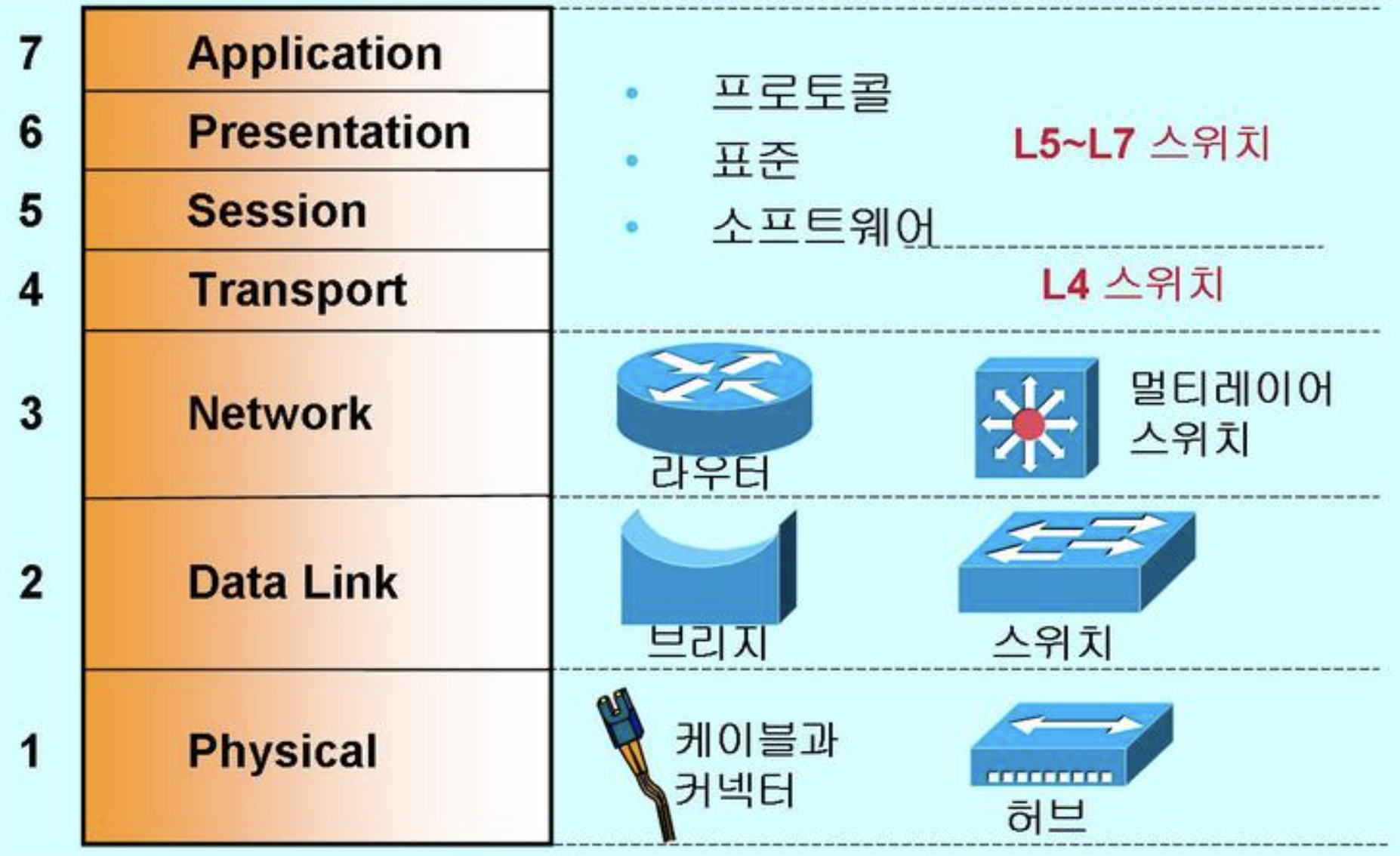
Repeater
A repeater operates only in the Physical Layer(L1) of the OSI 7 Layer model and amplifies weakened signals back to their original size due to the characteristics of LAN cables. Repeaters can overcome the distance limitations of LANs. For example, in 10Base2 and 10Base5 networks, up to four repeaters can be consecutively connected to extend the LAN. Currently, repeaters are not sold separately, as this functionality is included in hubs.
Bridge
A bridge operates in the Data Link Layer(L2) of the OSI 7 Layer model, particularly in the MAC Layer. It also has repeater functionality and can extend networks by connecting different networks located at long distances (e.g., Ethernet and Token Ring). Bridges do not generate traffic between segments if the source and destination are within the same segment. However, they cannot filter broadcast traffic, and they transmit data to the destination based on the MAC address of LAN cards.
Router
A router operates in the Network Layer(L3) of the OSI 7 Layer model. When dividing one LAN into multiple networks or connecting LANs through WAN, routers are utilized. Routers also include repeater and bridge functions. They find the fastest data transmission path between source and destination among multiple networks and separate traffic between each network. Traffic within the same network does not affect other networks; traffic passes through the router only when the source and destination are in different networks. Unlike bridges, routers can block broadcast traffic and use network addresses (e.g., IP addresses) to send data to the destination.
Summary
Topology
ways of connecting computers and other devices like switches and printers together
STAR Topology
STAR topology is characterized by a central host computer with direct connections to each computer. The advantage lies in its centralized network management approach, providing excellent flexibility for easy addition or removal of nodes. However, the drawback is that if the hub device fails, it causes a failure in the connected nodes, and the initial investment cost is high.
BUS Topology
Utilizing coaxial cables and connecting multiple hub devices, this method ensures that even if one node fails, it does not affect the network, making it easy to expand and cost-effective. However, drawbacks include distance limitations and lower performance.
RING Topology
Constructed in a closed circular shape, each node is attached to the rotating element. Data transmission in a RING topology involves stations waiting for their turn and transmitting packets. The advantage lies in its high performance and affordability, but a drawback is that if one node fails, the entire network experiences a failure.
Cabling and Connectors
Twisted pair
Typically, Unshielded Twisted Pair (UTP) cables are used as the foundation of the 10BASE-T method, with a supported distance of 100 meters.
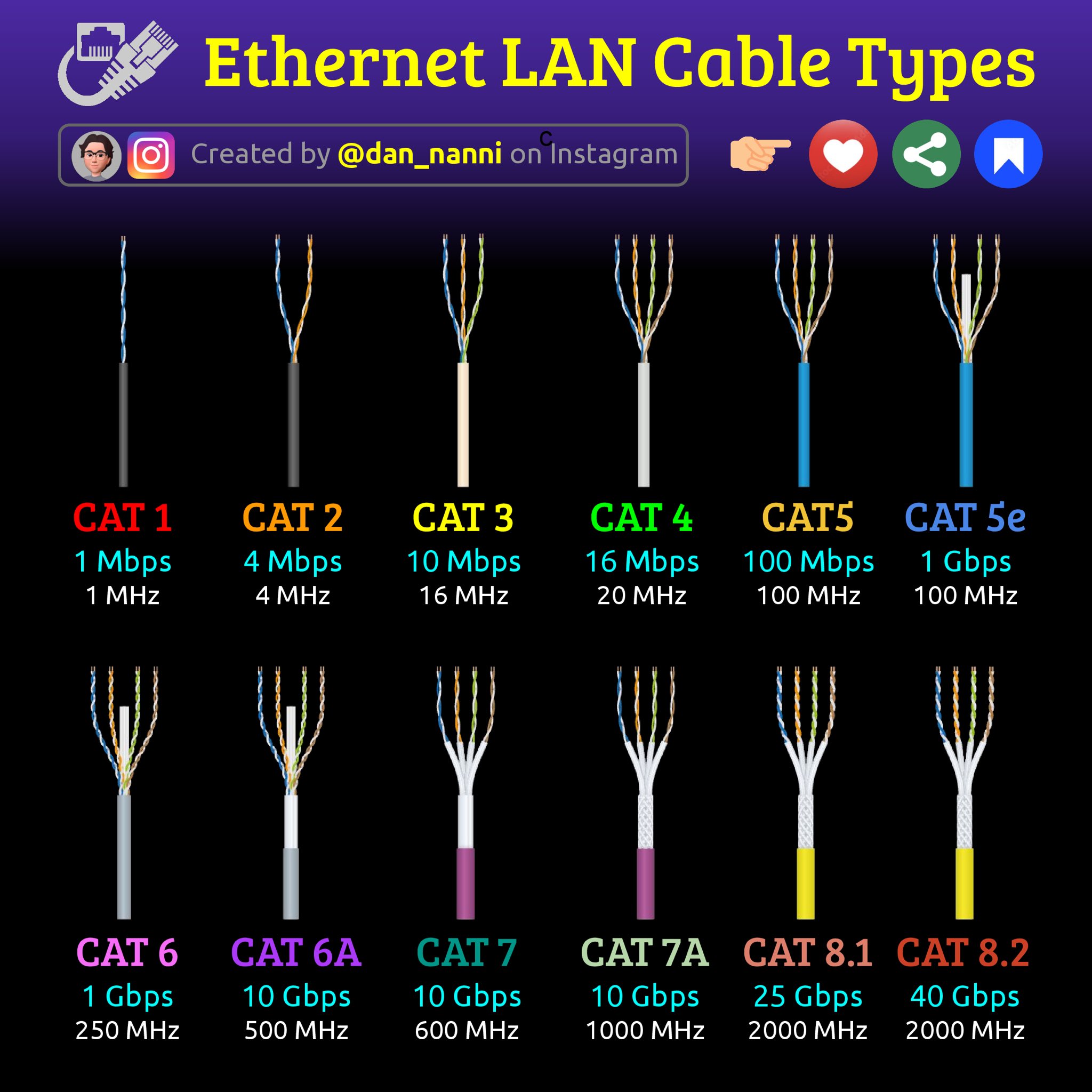
Categories
Twisted pair cables are categorized based on their performance characteristics, with Category 5e (Cat5e), Category 6 (Cat6), and Category 6a (Cat6a) being common variants. These categories denote the cable’s bandwidth, frequency, and data transmission capabilities.
Types
Twisted pair cables come in two main types: shielded twisted pair (STP) and unshielded twisted pair (UTP).
- Shielded Twisted Pair (STP): These cables have an additional layerof shielding, usually made of metal foil or braided wire, to protectagainst electromagnetic interference. STP cables are often used inenvironments with high levels of interference.
- Unshielded Twisted Pair (UTP): These cables lack additionalshielding and rely solely on the twisting of the wire pairs to reduceinterference. UTP cables are widely used in Ethernet networks due totheir cost-effectiveness and flexibility.
All UTP Ethernet NICs use the RJ-45 connector
Fiber-optic cable
Fiber-optic cable transmits light rather than electricity, making it attractive for both high-EMI areas and long-distance transmissions.
Types
Fiber-optic cables come in several types, each designed for specific applications:
- Single-mode fiber: This type of fiber has a smaller core diameterand allows a single mode of light to propagate, resulting in highbandwidth and long-distance transmission. It is commonly used inlong-distance telecommunications and high-speed data networks.
- Multimode fiber: Multimode fibers have a larger core diameter,allowing multiple modes of light to propagate simultaneously. Whileoffering lower bandwidth and shorter transmission distances compared tosingle-mode fibers, multimode fibers are suitable for shorter-distanceapplications such as local area networks (LANs) and premises cabling.
- Plastic optical fiber (POF): POF cables use plastic instead ofglass for the core and cladding. They are less expensive and easier toinstall than glass fibers but offer lower bandwidth and shortertransmission distances. POF is often used in applications such as homenetworking and automotive systems.
Ethernet Standards
Bus Ethernet
100BASE-T
10BASE-T used unshielded twisted pair (UTP) cabling. Although the cable has four pairs, 10BASE-T used only two of the pairs. 10BASE-T devices used pins 1 and 2 to send data, and pins 3 and 6 to receive data. Even though one pair of wires sent data and another received data, a 10BASE-T device that was connected to a hub could not send and receive simultaneously.
10BASE-T Summary
- Speed: 10 Mbps
- Signal type: Baseband
- Distance: 100 meters between the hub and the node
- Node limit: No more than 1024 nodes per hub
- Topology: Star-bus topology: physical star, logical bus
- Cable type: Cat 3 or better UTP cabling with RJ-45 connect
Ethernet LAN cable type