This post was written for
studying. There maybe a lot wrong going on.
목차
How NICs work?
You may interest: Network - LAN Synopsis
NIC stands for Network Interface Card. It’s a hardware component that enables a computer to connect to a network, such as a local area network (LAN) or the Internet.
Inside every NIC, burned onto some type of ROM chip, is special firmware containing a unique identifier with a 48-bit value called the media access control address, or MAC address.
Data Transmission and Reception
When the computer needs to send data over the network, the NIC receives the data from the computer’s CPU/RAM and converts it into a format suitable for transmission over the network medium. This process involves packetizing the data according to the appropriate network protocol (e.g., TCP/IP for Ethernet networks). The NIC then transmits these packets onto the network medium.
MAC Address Handling
Each NIC has a unique Media Access Control (MAC) address burned into its hardware. When sending data, the NIC encapsulates it with the MAC addresses of both the source (the computer’s NIC) and the destination (the intended recipient’s NIC). This addressing ensures that the data reaches the correct destination on the network.
Protocol Processing
NICs handle various networking protocols according to the communication standards supported by the network. For example, Ethernet NICs handle the Ethernet protocol, while Wi-Fi NICs handle Wi-Fi protocols like IEEE 802.11. The NIC interprets and processes these protocols to ensure that data is transmitted and received correctly.
Overall, NICs serve as the gateway between a computer and the network, facilitating the exchange of data and enabling communication with other devices on the network. Their efficient operation is essential for reliable network connectivity and optimal performance of networked applications and services.
Switch and Router, What’s different?
Switch has a MAC address on its NIC but is set to Promiscuous mode, allowing it to receive all frames regardless of MAC address.
A Router, unlike a switch, has a MAC address on its NIC and is configured with an IP address as well. Each interface of the router belongs to a different LAN. The Router’s NICs function similarly to those of typical IP devices and handle Ethernet frames in the following cases, forwarding them to the upper layers:
- When the Destination MAC address matches the MAC address of its own interface.
- When the Destination MAC address is a Broadcast MAC address.
- When the Destination MAC address is a Multicast MAC address.
There is a Receive mode called Promiscuous Mode in the MAC controller. For Window PCs or Linux/Unix Servers, the NIC’s Promiscuous Mode is usually disabled by default. When using tools like Wireshark or tcpdump to receive packet dumps, enabling the tool initiates Promiscuous Mode, allowing the NIC to accept all incoming frames without filtering based on MAC address. In L2 Switches, Promiscuous Mode is enabled on all ports. Therefore, the MAC controller accepts and forwards all Ethernet frames without filtering based on MAC addresses. This is why the MAC addresses of switching ports on L2 Switches are rarely used in actual communication, leading some people to occasionally wonder if L2 Switches lack MAC controllers.
Although L2 Switches accept all frames in Promiscuous mode, filtering occurs at the MAC controller level when VLAN Tag filtering is applied. Untagged ports reject VLAN Tagged frames, and Tagged ports filter frames with unauthorized VLAN tags.
Host to Host through a Switch
A Switch primarily has four functions: Learning, Flooding, Forwarding, and Filtering:
1. Learning
Being a Layer 2 device, a Switch will make all its decisions based upon information found in the L2 Header. Specifically, a Switch will use the Source MAC address and Destination MAC address to make its forwarding decisions.
One of the goals of the Switch is to create a MAC Address Table, mapping each of its switchports to the MAC address of the connected devices.
Technical Mechanisms
-
MAC Address Table Structure:
- The MAC address table (or Content Addressable Memory, CAM) typically contains:
- MAC Address: The unique identifier of the device.
- Port Number: The physical port on the switch where the device is connected.
- VLAN Identifier: If VLANs are used, the switch also associates MAC addresses with VLAN IDs to differentiate between devices in different broadcast domains.
- The MAC address table (or Content Addressable Memory, CAM) typically contains:
-
Learning Process:
- Each time a switch receives a frame:
- It examines the source MAC address.
- If the MAC address is not in the table, it adds a new entry with a timestamp.
- If the MAC address is already present but the associated port differs, the switch updates the port number.
- Each time a switch receives a frame:
-
Aging and Timers:
- Entries in the MAC address table have an aging timer. If a switch does not see a frame from a MAC address for a predefined period (often configurable, e.g., 300 seconds), the entry is removed to free up resources.
Protocols and Standards
- IEEE 802.3 (Ethernet): This standard governs the transmission of frames in Ethernet networks, and the learning function is inherent to how Ethernet switches operate.
2. Flooding
Technical Mechanisms
-
Broadcast Transmission:
- When a switch floods a frame, it sends it out all ports except the incoming port. This uses the broadcast MAC address (
FF:FF:FF:FF:FF:FF), which is recognized by all devices on the local segment.
- When a switch floods a frame, it sends it out all ports except the incoming port. This uses the broadcast MAC address (
-
Learning Through Flooding:
- When devices receive flooded frames, they typically respond (if applicable). For example, when a device receives a frame addressed to it for the first time, it will send a reply, allowing the switch to learn its location.
Protocols and Standards
- Ethernet Protocol: The flooding mechanism utilizes the Ethernet standard for broadcasting frames across the network.
3. Forwarding
Technical Mechanisms
-
Frame Processing Logic:
- When a switch receives a frame:
- It checks the destination MAC address against its MAC address table.
- If found, it forwards the frame out the corresponding port.
- If not found, it defaults to flooding.
- When a switch receives a frame:
-
Switching Techniques:
- Store-and-Forward Switching:
- The switch buffers the entire frame, checks for errors (using CRC), and then forwards the frame. This method minimizes the chance of forwarding corrupted frames but can introduce latency.
- Cut-Through Switching:
- The switch begins forwarding the frame as soon as it reads the destination MAC address. This reduces latency but may forward bad frames.
- Fragment-Free Switching:
- A hybrid approach where the switch reads the first 64 bytes of a frame (the collision zone) before forwarding, reducing the chances of forwarding collisions while still maintaining lower latency than store-and-forward.
- Store-and-Forward Switching:
Protocols and Standards
- IEEE 802.1D: This standard defines the operation of bridges and switches, specifying frame forwarding rules.
4. Filtering
Technical Mechanisms
-
Frame Evaluation:
- Switches evaluate incoming frames based on their destination MAC addresses, comparing them to the MAC address table. They also check for conditions that would require filtering:
- If the source and destination MAC addresses are the same (loop prevention).
- If VLAN filtering rules are applied (ensuring traffic only flows within the same VLAN).
- Switches evaluate incoming frames based on their destination MAC addresses, comparing them to the MAC address table. They also check for conditions that would require filtering:
-
Implementing Security Measures:
- Port security features can restrict which MAC addresses are allowed to communicate through specific ports, providing an additional layer of filtering.
Protocols and Standards
- IEEE 802.1Q: This standard specifies VLAN tagging, enabling switches to filter traffic based on VLAN membership and ensuring that traffic does not cross VLAN boundaries.
How These Functions Interact in a Network Scenario
-
Initial Communication:
- Host A sends data to Host B. Since Host B’s MAC is initially unknown to the switch, the switch floods the frame to all ports except the one Host A is connected to.
-
Learning and Flooding:
- When Host B responds, the switch learns its MAC address, associates it with a specific port, and updates its MAC table.
-
Subsequent Forwarding:
- The next time Host A communicates with Host B, the switch forwards frames directly to Host B’s port, reducing unnecessary traffic.
-
Filtering with VLANs:
- If Host A and Host B belong to separate VLANs, the switch filters frames to prevent cross-VLAN communication unless routing or inter-VLAN communication is specifically configured.
-
Ongoing Management:
- As the network grows, the switch dynamically updates its MAC table, filters traffic within VLANs, floods broadcasts or unknown MACs when needed, and forwards known traffic efficiently.
L2 Switch vs L3 Switch
Reference: Layer 2, Layer 3 & Layer 4 Switch: What’s the Difference?
Before explicitly configuring it to operate as an L3 Switch, a Layer 3 (L3) Switch operates as an L2 Switch. To function as an L2 Switch, the MAC controller’s Promiscuous Mode is enabled by default. Cisco L3 Switches can activate Inter-VLAN routing functionality by entering the command “ip routing”. By creating Switch Virtual Interfaces (SVIs) for each VLAN, IP routing becomes possible between different VLANs.
In an L3 Switch, ports belonging to the same VLAN operate as an L2 Switch, while nodes belonging to different VLANs function as routers. Even when operating as an L3 Switch by entering the “ip routing” command, ports belonging to the same VLAN can still operate as an L2 Switch. Thus, the MAC controller of the L3 Switch, like that of an L2 Switch, can utilize Promiscuous Mode to pass all Ethernet frames to the Network Processor (NP) and perform MAC filtering at the NP.
However, depending on the vendor’s implementation, Promiscuous Mode may be disabled when a specific port is explicitly configured as a routed port (similar to a router’s port, belonging to a single subnet with its own assigned IP address).
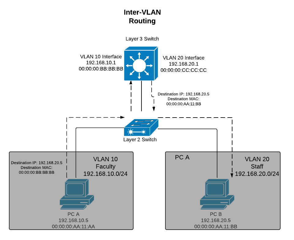
결론! L3 Swtich는 VLAN이 같은 port간에는 L2 Switch로 동작하고, 서로 다른 VLAN에 속하는 node들에게는 router로 동작함!
Subnet
Reference:Networking: OSI layer 3
Mac adresses work for small network, but what happens when the network gets big, like the size of the entire internet? When networks get large, you can’t use the MAC addresses anymore. Large networks need a logical addressing method that ignores the hardware and enables you to break up the entire large network into smaller networks called subnets
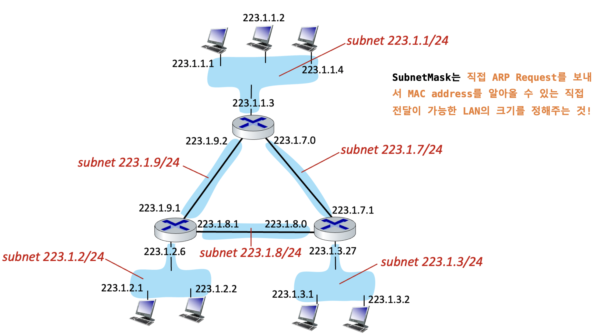
Detach each interface form its host or router, creating “islands” of isolated networks each isolated network is Subnet